Table of Contents
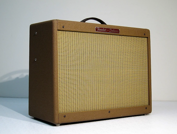
Fender HotRod Bugfix Collection
My tips and tricks collection for tackling Fender HotRod issues - 2023 Edition
All those tricks have been applied to my personal HotRod with great success, most illustrations comping from this experience.
General warning : All the suggestions, tips and tricks listed on this page are potentially dangerous for anyone's health and could damage/destroy your amp. Author cannot be held any responsibility related to any damage/issue/accident arising following the suggestions listed here.
Disclaimer on opening any Amp : Just consider taking your Hotrod to an Amp shop. All the suggestions in this section are targeting those who have basic knowhow of electronics, soldering and high voltage designs. Opening your amp exposes you to high voltage which is extremely dangerous. Do it at your own risks. The intent here is to list all potential root causes and corrective actions to help investigating your own issues.
Forewords : To mod HotRod or to not mod HotRod
All these steps have been performed on a ~2000 Special edition Fender HotRod Deluxe, however most of the design characteristics and recommandations listed here apply to every model of the HotRod series, namely:
- Blues Junior
- Blues Junior III
- Hot Rod Deluxe
- Hot Rod Deluxe Rev A
- Hot Rod Deluxe 112
- Hot Rod DeVille
- Hot Rod DeVille Rev A
- Hot Rod DeVille Rev B
- Hot Rod Deluxe & DeVille III
- Pro Junior
- Pro Junior III
- Woody Pro Junior 60th Anniversary
Removing HotRod's back plate
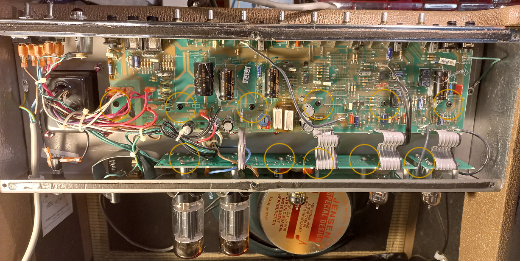
To access internal design, remove the 6 back screws and remove the back plate.
Isn't it cute?
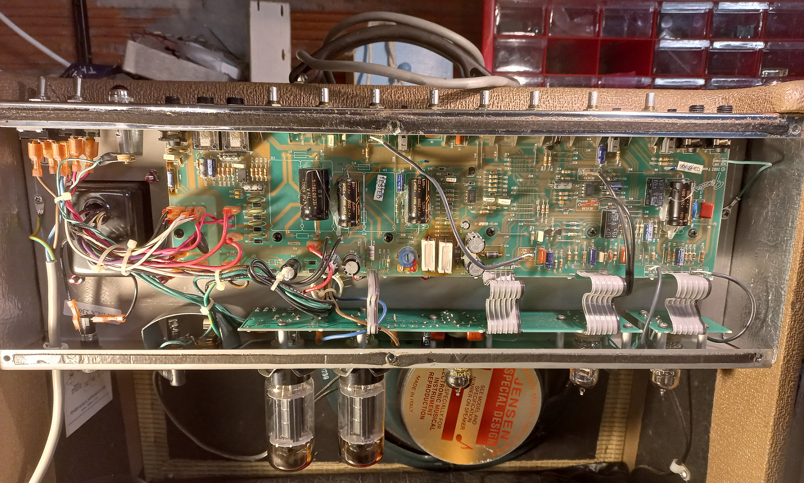
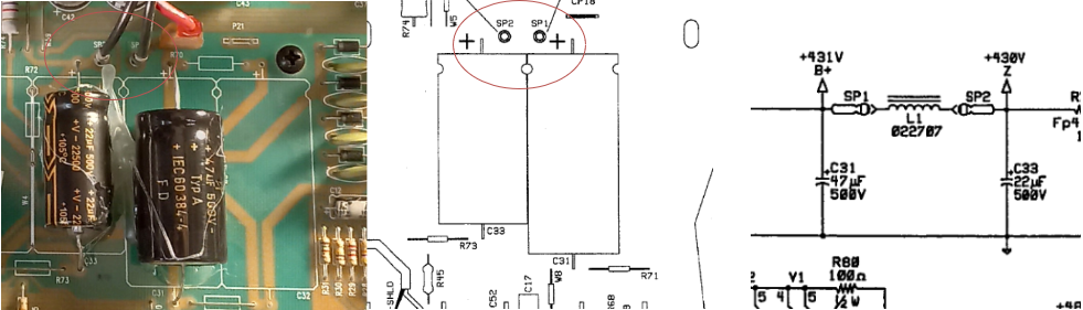
The first thing to do after every panel removal/power cycle is to check that power capacitors are properly soaked. Using a voltmeter on 300V+ setting, check that the residual voltage on SP1 is lower than 12V. If not, discharge C31 using a 50k-1W Resistor between its leads.
Bugfix #0 : Cleaning
Bugfix #1 : Tighten them all
First and foremost, especially you own an old Hotrod, all inner and outer screws need a check if you experience any form of rattling. Take a screwdriver and apply a reasonable torque on each of them.
Front Screws
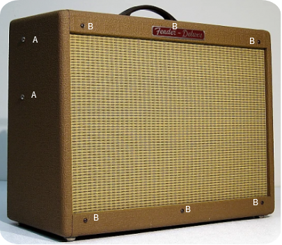
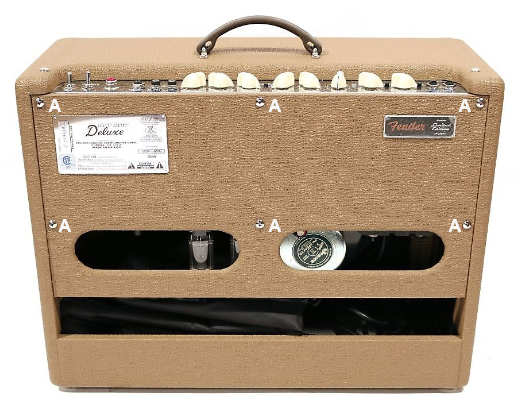
First, mind those main body screws labeled A. Check the side and back screws first, and then handle top handle screws.
The ones on the front - labeled B which hold the speaker holding front face - require special attention, since that front face behind the cloth is a quite thin piece of wood. There are several reported rattles that came from those screws.
There are 6 of them. Yes, six. The top middle one is hidden behind the “Deluxe” label. You don't need to remove it though, just check from behind that the nut is well tightened.
Here is what it look like from the inside:
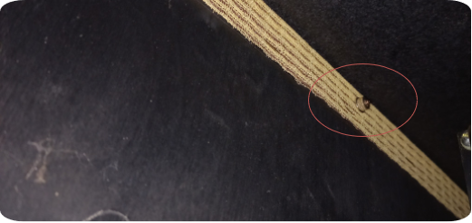
Check on both sides for proper nut installation. Mine had 2 missing nuts (yes, TWO) which lead to the front face rattling like hell. Thankfully they are pretty standard M4 ones.
Speaker plate
Tighten Speaker screws first, from the inside.
Speaker plate can be strenghtened, here is a custom angle stiffener that can be installed inside the amp, one on each side. It helped clearing front face vibrations.
Download STL Files :amp_hold.zip
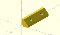
I consider 6 front screws being not enough for this kind of amp, especially if you look at the distance between top and bottom screws on each side. This is 40W tube amp after all!
Find a 3D printer and print 4 of those, one for each face. Mount them internally, between front plate and chassis.
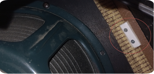
Install them using short screws at 45° angle, here is what it looks like from the inside.
Internal Screws
Should you open the amp, this is an excellent opportunity to tighten all internal screws, as illustratead below.
- Check all lose PCB screws,
- Check input, output and choke transformer screws as well. These can be hard to access internally.
Don't forget to tighten the transformer screws as well.
Bugfix #2 - Checking Tubes
Detecting and changing broken/damaged tubes
Then, failed tubes can cause rattle so we need to check them. This is generally linked to some inner part mechnically broken, but still electronically connected leading to vibration-induced noise. Power-on the amp and take any kind of chopstick. Put the amp volume to 2 and softly - extremely softly - tap the preamp and power tubes. You should not hear anything on the speaker. If you hear some sort of dull tick with a damped ringy reverb, then you might have some failed tube ringing issues. Change the ringing ones with a replacement one.
Dampening preamp tubes - easy rubber mod
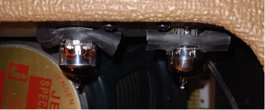
If your preamp tubes were not provided with damper rubber sleeves, grab an old bike inner tube and some scisors, and cut out three rubber damper first. Install these on your preamp tubes as shown to prevent any form of rattling coming from tube mechanical coupling with the case.
Here is what it looks like when installed:
Bugfix #3 - Refresh soldering
HotRod's PCB quality is highly questionable, leading to several component/soldering issue. This section tackles mspecifically soldering and PCB problems.
Rework solder joints
Inspect PCB and look for suspicious solder joints as per those detailed here https://meyerems.com/effective-soldering-iron-rework/
You want to investigate in priority the following components:
Critical heating components
- Low voltage power resistors R78 and R79 can get really hot and their solder joints are stressed a lot. Inspect these first.
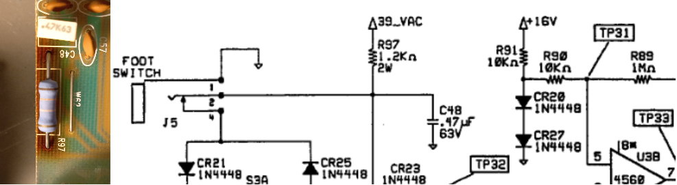
- Footswitch cricuit R97 is a good candidate too. Heats a lot.
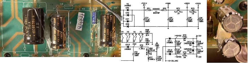
- Inspect all polarisation resistors in PCB, especially R4, R11, R16, R57, R58, R61, R62, and eventually power resistors R74 and R75.
Capacitors
- power capacitors C31, C33, C35, C36, C40, C41 are large capacitors on which vibrations tend to stress solder joints. Inspect and rework them if needed.
Apply solder paste on weakened tracks
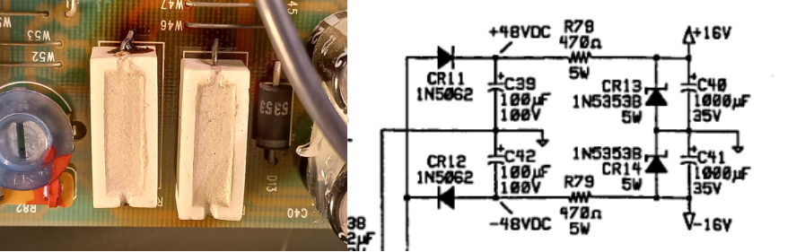
Strengthen damaged tracks/PCB with solder on tracks. In case a spot looks weakened (especially on critical heating components), consider creating solder tracks as shown :
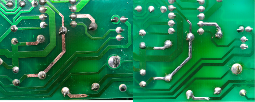 Example of HotRod's 5W PSU resistors with strengthened copper tracks - Source Music Electronics Forum
Simply scratch the varnish over tracks using a sharp knife to reveal raw track copper, clean with alcohol/acetone, and then apply solder paste using iron.
Bugfix #4 - Replacing and strengthening PCB components
The components listed in this section are worth replacing if any damage or sound issue is identified.
There are some complete replacement kits avaiable on the internet, which include all components that are generally worth upgrading.
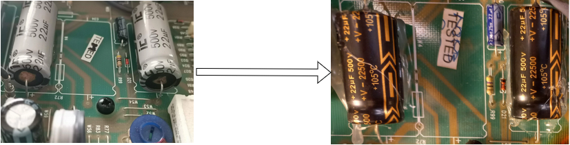
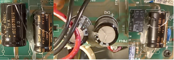
Replace power capacitors
If your main power capacitors are from the IC brand, generally shipped in light grey as shown below, they are low quality chinese capacitors which are prone to leak, seriously reducing amp performance.
Consider replacing them with same value/voltage rating (FT, etc…).
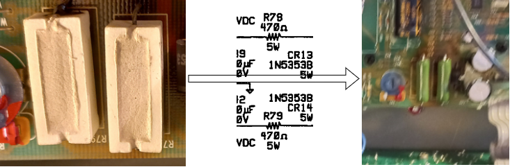
Replace burnt resistors
Resistors R78 and R79 of the low voltage part are 5W 470 Ohms, but are exposed to transients up to 4.9W (48V@470Ohms). Upgrading these to higher quality 10W wired resistors is encouraged. Notably, installing the resistors slightly above PCB to increase air flow is recommended.
Bugfix #5 - Glue them all
If not implemented, use RTV glue to fix large components, including all big capacitors.
Generally, medium sized capacitors from Power Supply are not glued and I suggest to glue them, because radial capacitors are sensitive to vibrations and this amp is really punchy.
Resources:
- Service Manual - hot_rod_deluxe.pdf
- Date your amp - https://www.guitarinsite.nl/serienummers-fender-amps_eng.php
- Accutronics Reverb reference guide - https://www.amplifiedparts.com/tech-articles/accutronics-products-and-specifications
Top image © Vintage Gear America - Palmdale, CA